Application / technical article
Planning Concealed Connections for Drawer Boxes: Panel Relationships, Machining Access and Assembly Direction
Plan concealed drawer box connections by defining panel relationships, visible faces, machining access and final assembly direction before selecting a connector.
Quick answer
What You Need to Know
Start by mapping which panel faces stay visible, how each panel meets its neighbour, and which machine will reach each joint. Then choose a connector whose machining method and panel thickness range match that plan. Tool-free final assembly still requires CNC drilling or grooving and connector pre-installation before the box is closed.
Key takeaways
- Define visible faces and joint types before selecting a connector.
- Match connector machining method to your available CNC operations.
- Check panel thickness against the connector's stated range.
- Plan assembly direction so pre-installed connectors remain accessible.
- Validate pull-out and shear performance in your actual board material.
Panel relationships and visible faces
Drawer boxes and cabinet interiors rarely show every joint. Before choosing a connector, mark which faces remain visible after assembly: the drawer front, the outer sides, the top edges and the interior base. Joints that fall on visible faces usually call for a concealed connector, while joints hidden inside the box or behind a fixed panel give more freedom in machining and access.
Next, describe how each panel meets its neighbour. A drawer side meeting a front panel is typically a corner joint; a base meeting sides and front is a panel-to-panel joint along an edge. Record whether the joint is load-bearing, whether it must resist pull-out, and whether the panels are solid wood, plywood, particleboard or MDF. These relationships determine the connector type and the machining direction.
Sketch the box in exploded view and label each joint with its visible face, panel thickness and expected load. This sketch becomes the reference for machining setup and assembly sequence, and it prevents later changes from forcing a connector that no longer fits the joint.
- Mark every face that remains visible after final assembly.
- Classify each joint as corner, edge-to-face or panel-to-panel.
- Note panel thickness at each joint before selecting a connector.
- Identify joints that carry drawer load or resist pull-out.
Machining access and connector selection
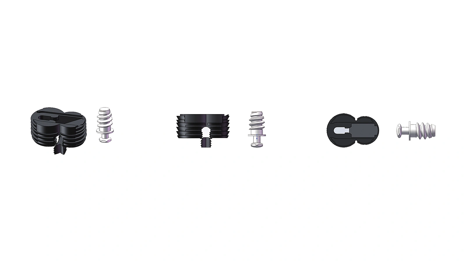
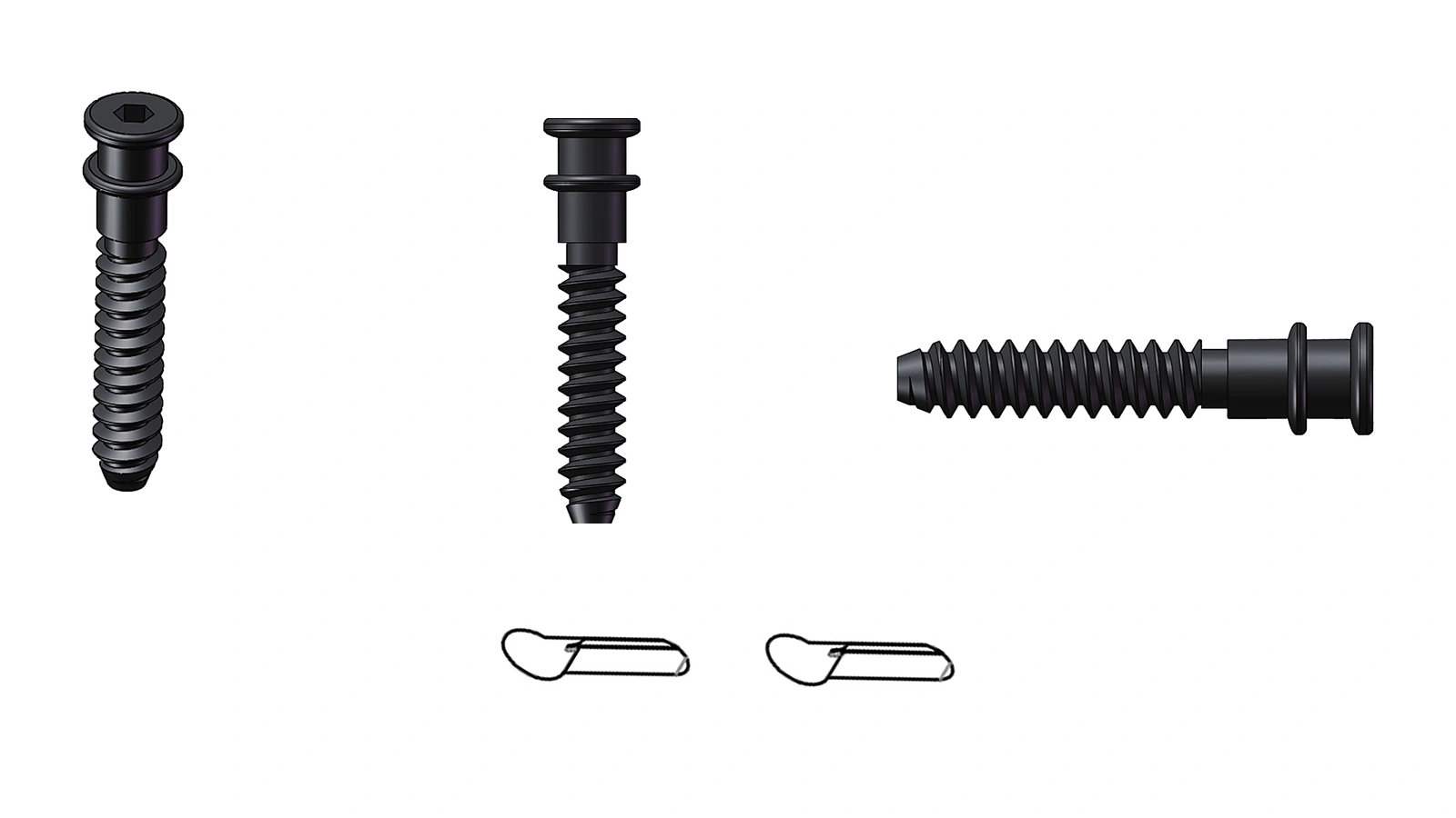
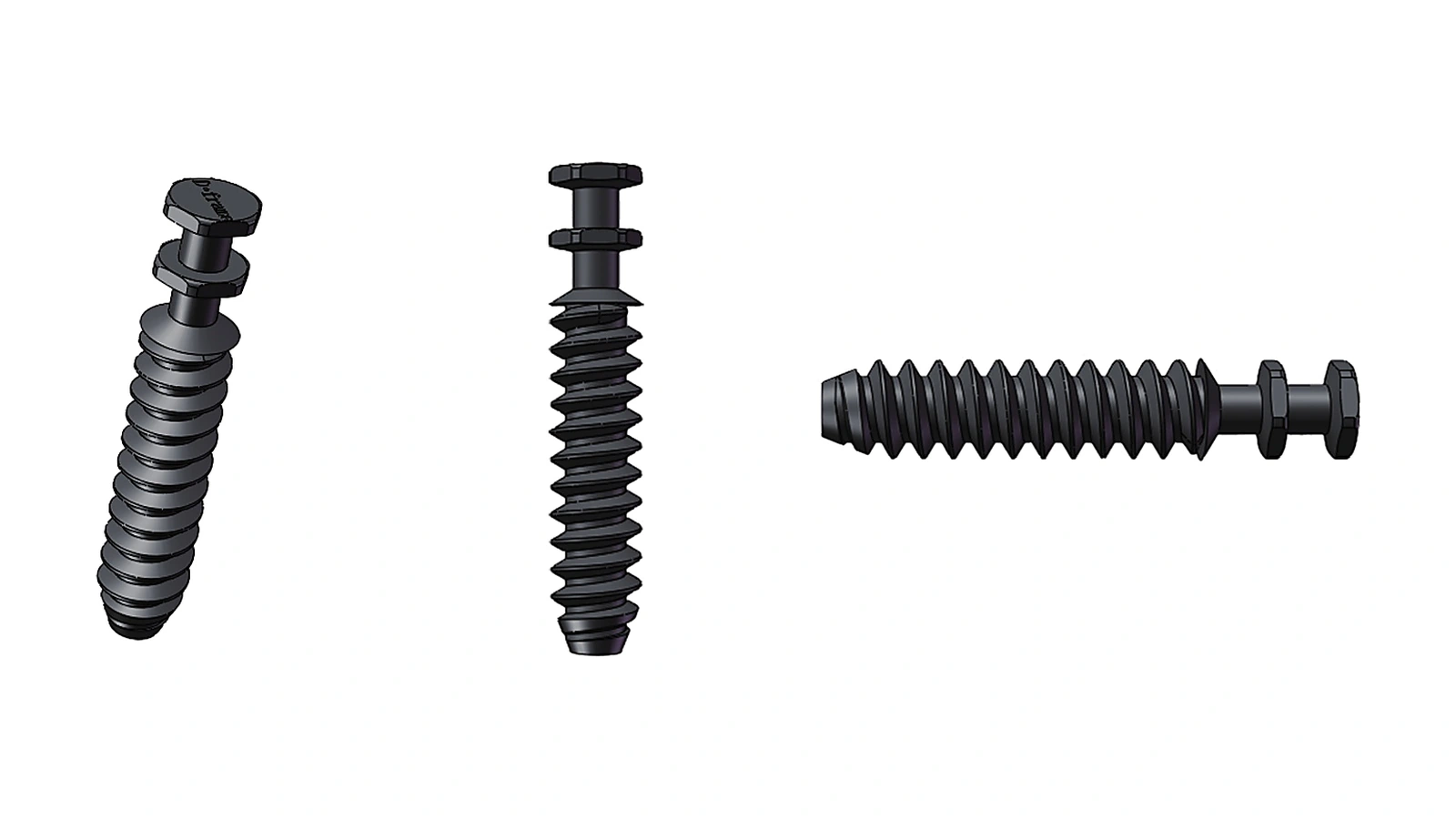
Machining access decides which connector family is practical. A drilling-type connector such as D001 requires drill access perpendicular to the panel face, while grooving-type connectors such as S001 and S002 require a slot or groove along the panel edge or face. If your CNC cell is set up for drilling but not grooving, a drilling connector keeps the process inside existing capability; if grooving is already part of the workflow, a grooving connector may suit the joint geometry better.
Panel thickness narrows the choice further. D001 is intended for 16–25 mm panels, S001 for 12–18 mm panels and S002 for 18–36 mm panels. Check the actual thickness of each panel at the joint, not the nominal board size, because veneered or laminated panels can differ. A connector outside its stated range should not be forced into the design.
Published performance figures help compare models but do not replace joint testing. D001 lists 700 N tensile, 260 kg shear and 200 N anti-detachment; S001 and S002 each list 900 N tensile, 260 kg shear and 200 N anti-detachment. Use these as comparison inputs and validate the chosen connector in the intended board material and joint configuration.
- D001: drilling method, 16–25 mm panels, 700 N tensile, 260 kg shear, 200 N anti-detachment.
- S001: grooving method, 12–18 mm panels, 900 N tensile, 260 kg shear, 200 N anti-detachment.
- S002: grooving method, 18–36 mm panels, 900 N tensile, 260 kg shear, 200 N anti-detachment.
- Confirm that your CNC can reach each joint without repositioning that distorts the reference edge.
Assembly direction and pre-installation
Final assembly direction determines whether pre-installed connectors remain reachable. In a drawer box, the base often closes the box last, so connectors between the base and the sides must be pre-installed and engaged as the base slides into place. If the front panel is added last, its connectors must be accessible from the front or through an opening that will later be covered.
Tool-free final assembly refers to the closing stage only. Before that, CNC drilling or grooving and connector pre-installation still take place. Plan the sequence so that each connector is fixed to one panel, the mating feature is machined in the other, and the two panels can be brought together in the intended direction without trapping the connector or requiring force.
A simple assembly sequence diagram, showing which panel moves and in which direction at each step, exposes conflicts early. If a connector cannot be engaged in the planned direction, either the joint geometry or the connector family needs revisiting before production.
- 01List the order in which panels are joined during final assembly.
- 02For each joint, identify which panel carries the pre-installed connector.
- 03Confirm that the mating panel can move into position without obstructing the connector.
- 04Check that no later panel blocks access to a connector that still needs engagement.
- 05Mark any joint where assembly direction conflicts with connector orientation.
Validation and production checks
Before releasing a drawer box design to production, build a sample using the actual board material, thickness and joint configuration. Test the joints that carry load or resist pull-out, and compare the results with the published figures for the chosen connector. Board density, face material and machining quality can all affect performance, so a sample test is the only reliable confirmation for your specific construction.
On the production line, verify that drilling depth or groove position matches the connector's requirements and that pre-installed connectors sit flush. A small offset can prevent tool-free engagement or reduce joint strength. Include these checks in the first-article inspection and in periodic production audits.
If a joint falls outside the connector's stated panel thickness range or cannot be machined with the available equipment, revisit the panel relationship or consider a different connector family rather than modifying the connector or forcing the fit.
- Test a sample joint in the production board material and thickness.
- Compare sample results with published tensile, shear and anti-detachment figures.
- Inspect drilling depth or groove position at first article and during production.
- Confirm pre-installed connectors sit flush and engage without force.
Connector comparison
Referenced models
Compare suitable connector models by application, panel thickness and machining method.
Practical questions
Frequently asked questions
Can I use a drilling connector and a grooving connector in the same drawer box?
Each connector family has its own machining path, and combining drilling and grooving operations in one box should be evaluated against your production equipment and joint plan. The published application records cover full cabinet assembly for each model individually; they do not confirm mixed-family use in a single drawer box. If you need to mix families, test the complete joint arrangement in a sample before production.
How do I choose between S001 and S002 for a drawer box?
The main difference is panel thickness range: S001 is intended for 12–18 mm panels and S002 for 18–36 mm panels. Both are grooving-type connectors with the same published tensile, shear and anti-detachment figures. Measure the actual thickness of the panels at each joint and select the model whose range covers that thickness.
Does tool-free assembly mean no machining is needed?
No. Tool-free refers to the final assembly stage, when panels are joined without tools. Before that, the panels still require CNC drilling or grooving, and the connectors must be pre-installed. Planning machining access and pre-installation sequence remains part of the production process.
What should I check before approving a drawer box design for production?
Build a sample with the actual board material and thickness, test the load-bearing and pull-out joints, and compare results with the published figures for the chosen connector. Also verify that drilling depth or groove position matches the connector requirements and that pre-installed connectors engage smoothly during final assembly.
Next steps