Selection / technical article
Actual Panel Thickness and Application-Specific Ranges in Concealed Connector Selection
Nominal board labels hide real thickness variation. Match concealed connectors to measured panel thickness and joint type before committing to CNC programs.
Quick answer
What You Need to Know
Select a concealed connector by the measured thickness of the panel it will sit in and by the joint it will form, not by the nominal board name. D001, D001-9 and D002 cover 16–25 mm drilling applications, while S001 covers 12–18 mm and S002 covers 18–36 mm grooving applications. D001-9 narrows to 18–25 mm for 45° miter joints.
Key takeaways
- A nominal 18 mm board can sit near the edge of one connector range and comfortably inside another.
- D001-9 has different ranges for its two joints: 18–25 mm for 45° miters and 16–25 mm for surface-to-surface connections.
- Drilling models (D001, D001-9, D002) and grooving models (S001, S002) suit different machining paths, so thickness alone does not decide the choice.
- Tool-free final assembly still requires CNC drilling or grooving and connector pre-installation before the cabinet is closed.
- Published tensile and anti-detachment figures are comparison inputs; validate the joint in the intended board material.
Why the Nominal Board Label Is Not Enough
A board sold as 18 mm is a nominal description, not a measured dimension. Thickness varies by supplier, by batch and across the sheet, and a panel that measures slightly under or over its nominal value can fall outside a connector's stated range or sit right at its boundary. When that happens, the machining program, the connector seating and the final joint all inherit the mismatch.
The practical consequence is that two panels from different suppliers, both called 18 mm, may not accept the same connector. One may sit comfortably inside a 16–25 mm drilling range; another may be at the lower edge of an 18–36 mm grooving range. Selection therefore starts with the measured thickness of the actual production board, not the label on the purchase order.
This matters most at range boundaries. A connector rated for 16–25 mm panels is intended for panels within that span, and a board measuring below 16 mm is outside it regardless of what the nominal description says. Confirm the measured thickness of each board type before shortlisting.
- Measure the production board, not a sample from an earlier batch.
- Check thickness at several points across the sheet, since variation within a panel affects seating.
- Record the measured range for each board type used in the cabinet.
- Treat a board at the edge of a connector range as a boundary case that needs a closer look.
Drilling Connectors: D001, D001-9 and D002
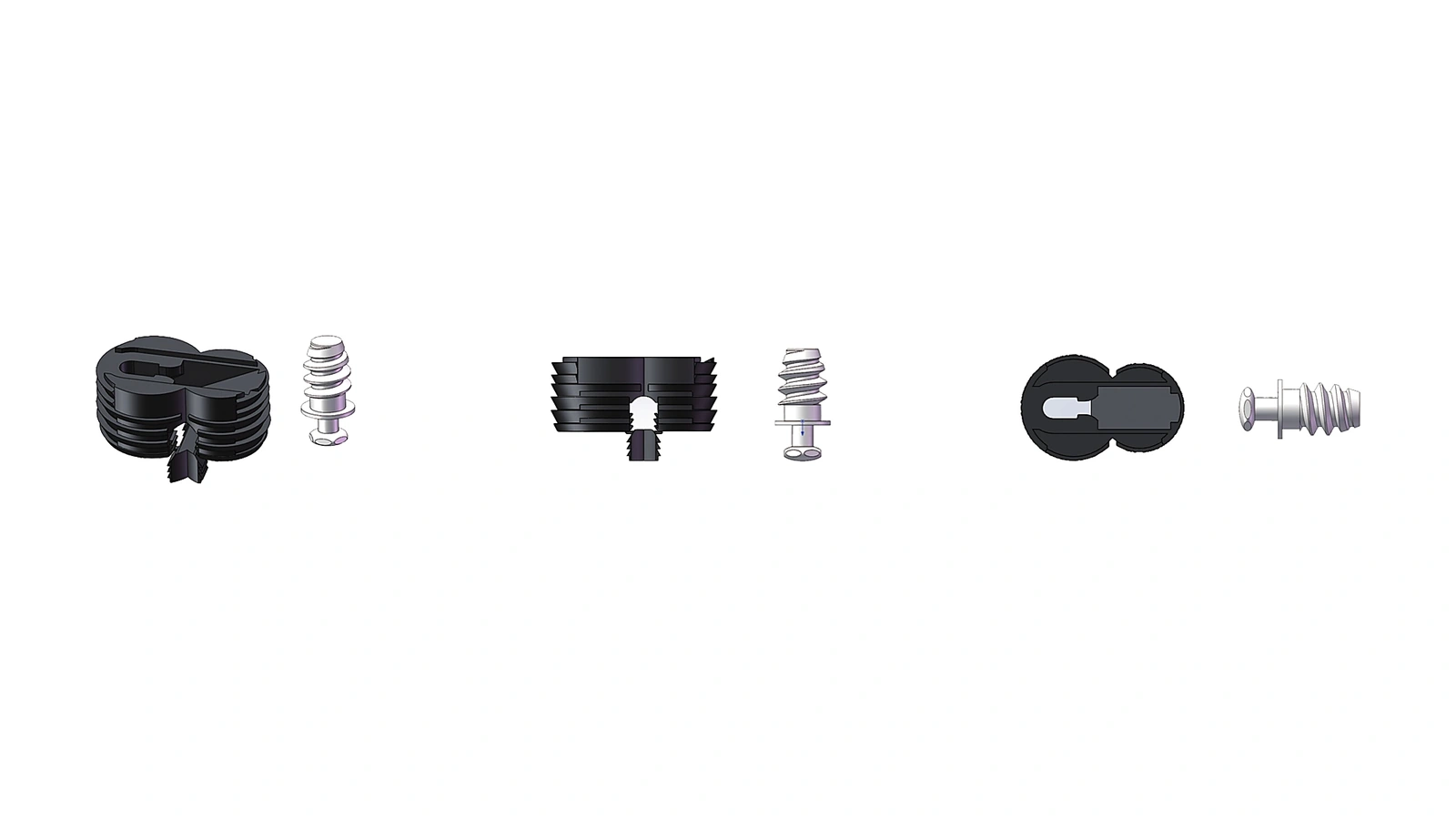
The drilling models share a 16–25 mm panel range for full cabinet assembly, which makes them candidates for the common 18 mm cabinet panel and for boards up to 25 mm. D001 and D002 are both intended for full cabinet assembly with a drilling-led process, and both are pre-installed before final assembly. The choice between them is a question of which model suits your cabinet design and machining setup, not of thickness alone.
D001-9 is the exception that shows why application-specific ranges matter. For a 45° miter joint its range is 18–25 mm, while for a surface-to-surface connection it is 16–25 mm. A 17 mm panel is therefore inside the surface-to-surface range but outside the miter range. If your cabinet uses both joints, the miter range governs the thinner boards.
All three drilling models list a tensile figure of 700 N and an anti-detachment figure of 200 N for their listed applications. These are comparison inputs for shortlisting, not a guarantee for every board material or joint geometry. A drilling path also means the CNC program must include the drilling operations and the connector must be pre-installed before the cabinet is closed.
- D001: full cabinet assembly, 16–25 mm, drilling.
- D001-9: 45° miter joint 18–25 mm; surface-to-surface connection 16–25 mm, drilling.
- D002: full cabinet assembly, 16–25 mm, drilling.
- Tensile 700 N and anti-detachment 200 N are listed for these applications.
Grooving Connectors: S001 and S002
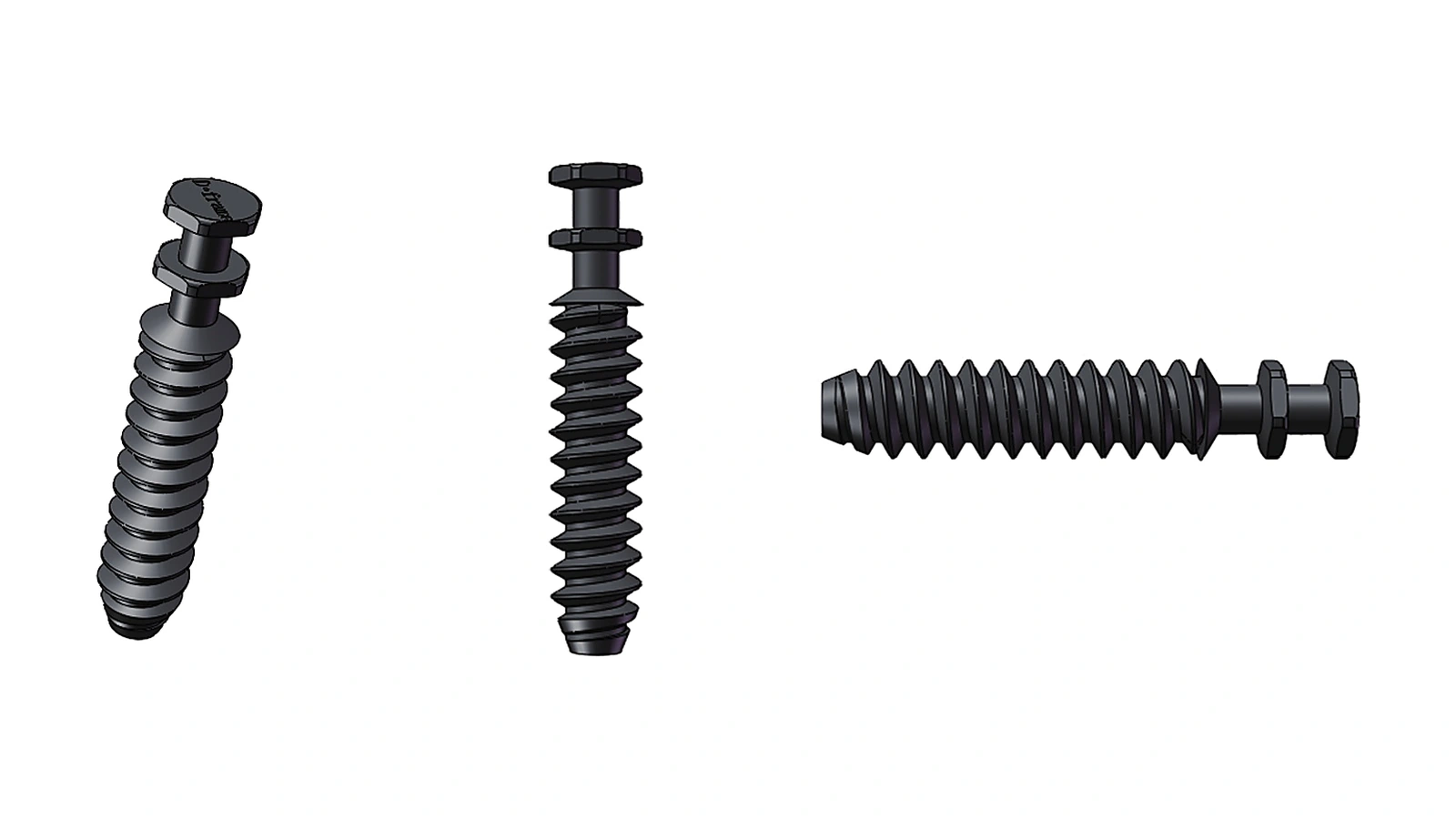
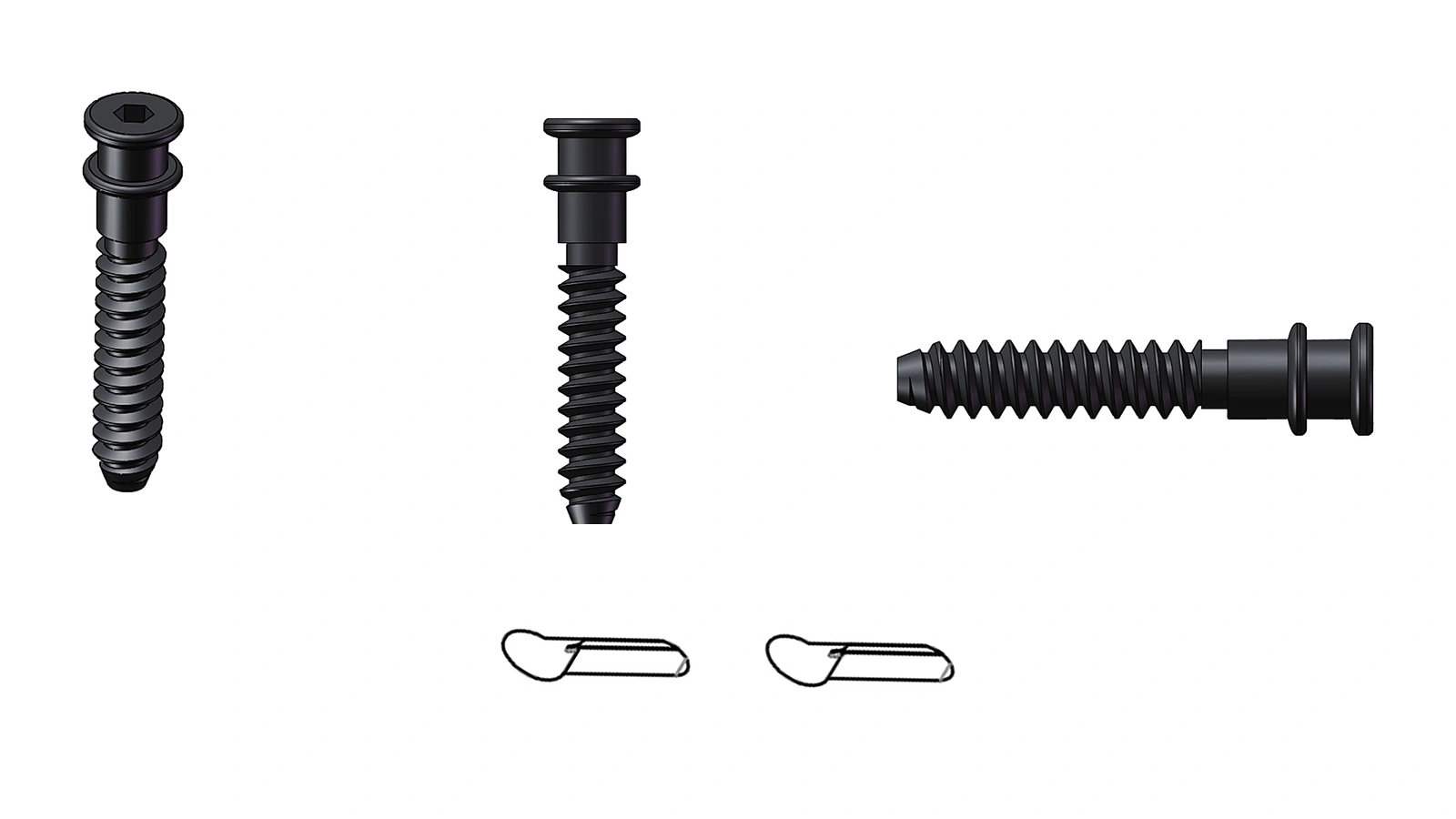
The grooving models split the thickness spectrum rather than overlapping it. S001 covers 12–18 mm panels for full cabinet assembly, which suits thinner constructions, while S002 covers 18–36 mm for thicker panels. An 18 mm board sits at the top of the S001 range and at the bottom of the S002 range, so the measured thickness decides which side of that boundary the board falls on.
Both grooving models list a tensile figure of 900 N and an anti-detachment figure of 200 N for full cabinet assembly. As with the drilling models, these figures are useful for comparing candidates but should be validated in the intended board material and joint. The grooving path also changes the production sequence: the slot must be machined and the connector pre-installed before final assembly.
Because the two grooving ranges meet at 18 mm, a production line that uses boards on both sides of that value needs a clear rule for which model applies. Measuring the board and recording the result against the connector range is more reliable than assuming that a nominal 18 mm board belongs to one model or the other.
- S001: full cabinet assembly, 12–18 mm, grooving.
- S002: full cabinet assembly, 18–36 mm, grooving.
- Tensile 900 N and anti-detachment 200 N are listed for these applications.
- The 18 mm boundary is shared, so measured thickness decides the model.
Machining Path and What Tool-Free Assembly Really Means
Tool-free refers to the final assembly of the furniture, not to production. Every model in this range requires CNC drilling or grooving and connector pre-installation before the cabinet is assembled. The drilling models need drilled holes; the grooving models need a machined slot. The choice between drilling and grooving is therefore a production decision as much as a thickness decision.
If your CNC setup is built around drilling, the D001, D001-9 and D002 range is the natural starting point, subject to the measured panel thickness. If it is built around grooving or slotting, S001 and S002 cover thinner and thicker panels respectively. Each joint must be checked against the range for its own connector and joint type.
The connector must be pre-installed before final assembly, which means the machining program and the pre-installation step both need to be confirmed before production begins. A connector that is correct for the panel thickness but incompatible with the machining path will still cause problems on the line.
- 01Measure the production board and record its thickness range.
- 02Identify each joint type in the cabinet, including any 45° miters.
- 03Match each joint to a connector whose application-specific range contains the measured thickness.
- 04Confirm the machining path (drilling or grooving) and program the corresponding operations.
- 05Pre-install the connectors before final assembly.
Validation Before You Commit
Published force figures help compare candidates, but they do not replace a check in the actual board material and joint. Board density, substrate and joint geometry all affect how a connector performs, and a figure listed for one application should not be assumed to transfer unchanged to another. Build a sample joint in the production material and load it in the way the cabinet will be loaded.
Where a board sits at the edge of a range, or where a joint type is not covered by the listed applications, the right next step is to ask for the relevant test documentation rather than to extrapolate. The same applies to any figure whose test method is not stated: request the method before relying on the number in a specification.
For teams shortlisting across several models, the connector selector and the full model comparison are the quickest way to narrow the field by thickness and machining path. Where a cabinet combines joint types or unusual board thicknesses, an engineering conversation is more efficient than guessing at the boundary.
- Test a sample joint in the intended board material.
- Request test documentation for any figure you intend to specify.
- Check boundary thicknesses against the application-specific range, not the nominal label.
Connector comparison
Referenced models
Compare suitable connector models by application, panel thickness and machining method.
| Model | Process | Application and panel range |
|---|---|---|
| D001 | Drilling |
|
| D001-9 | Drilling |
|
| D002 | Drilling |
|
| S001 | Slotting / grooving |
|
| S002 | Slotting / grooving |
|
Practical questions
Frequently asked questions
Can I use an 18 mm nominal board with any connector in this range?
Not automatically. An 18 mm nominal board may measure above or below 18 mm, and that measured value decides whether it falls inside a given connector's range. It sits at the top of the S001 grooving range and the bottom of the S002 grooving range, and inside the 16–25 mm drilling range but at the lower edge of the D001-9 miter range. Measure the board and check it against the specific application.
Why does D001-9 have two different thickness ranges?
Because the joint type changes the geometry. D001-9 covers 18–25 mm for 45° miter joints and 16–25 mm for surface-to-surface connections. A board between 16 and 18 mm is therefore suitable for a surface-to-surface connection but not for a miter joint with this model.
Does tool-free assembly mean no machining is needed?
No. Tool-free refers to the final assembly of the furniture. CNC drilling or grooving and connector pre-installation are still required before the cabinet is assembled. The drilling models need drilled holes and the grooving models need a machined slot.
Are the published force figures guarantees for my board?
They are comparison inputs, not universal guarantees. The listed tensile and anti-detachment figures apply to the listed applications, and performance depends on the board material, substrate and joint geometry. Validate the joint in the intended material before committing to production.
Next steps