Manufacturing / technical article
Concealed Connector Sample Validation Checklist: From Joint Drawing to Recorded Observations
A repeatable sample-validation workflow for concealed connectors, covering joint drawing, board material, machining, pre-installation, and final engagement.
Quick answer
What You Need to Know
Build a representative joint using the intended board material, panel thickness and drilling or grooving process. Check connector pre-installation, final engagement and joint fit before approving the assembly for production.
Key takeaways
- Tool-free final assembly does not mean machining-free production: CNC drilling or grooving and connector pre-installation still occur before final assembly.
- Match the sample to production board material and actual thickness, not just the nominal panel range.
- Record observations at each step: joint drawing, machining, pre-installation, final engagement, and any load checks.
- Treat published tensile, shear, and anti-detachment values as comparison inputs, not universal guarantees.
- Use published load figures only with an appropriate test basis and validation for your specific joint.
Define the joint and board before you cut anything
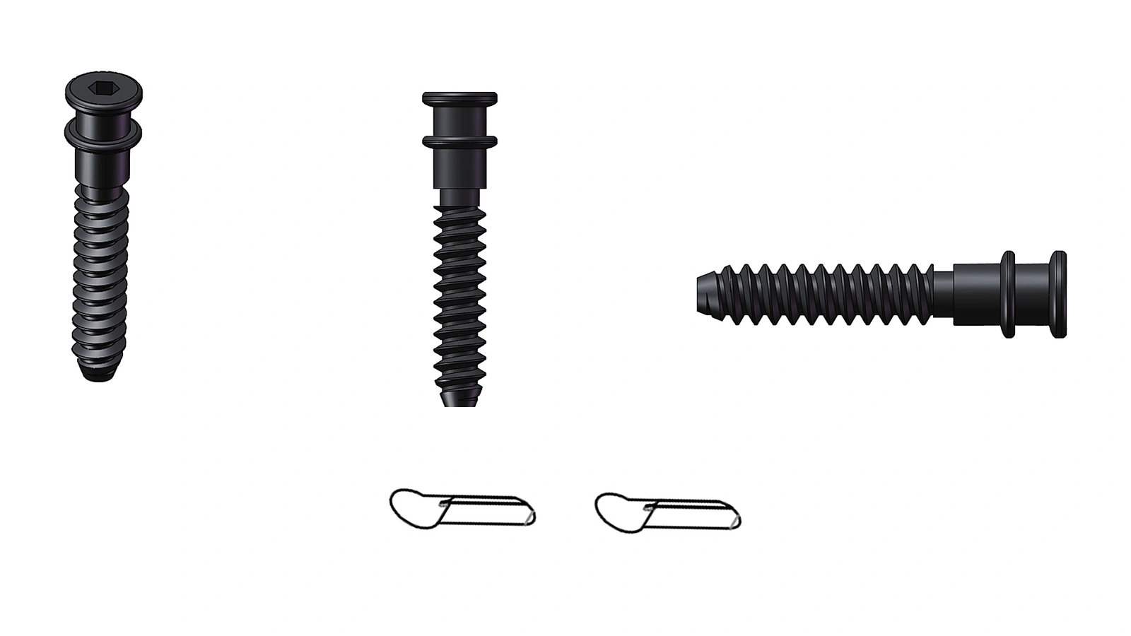
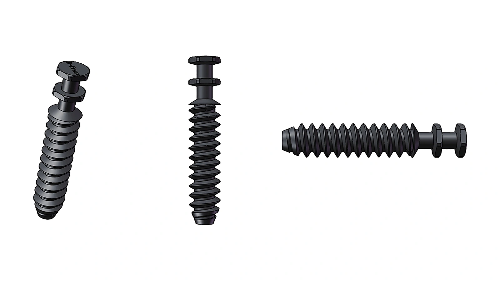
Start with a drawing that fixes the joint type, panel thickness, and connector orientation. For D001 and S001, the application is full cabinet assembly; for D001-9 and S001-9, the joint may be a 45° miter or a surface-to-surface connection, and the panel range differs by application. Write the intended application on the drawing so the sample is not evaluated against the wrong range.
Record the board material and the actual measured thickness of each panel. The catalog ranges are 16–25 mm for D001, 18–25 mm for D001-9 miter joints, 16–25 mm for D001-9 surface-to-surface joints, 12–18 mm for S001, 18–25 mm for S001-9 miter joints, and 12–18 mm for S001-9 surface-to-surface joints. A sample built from a different substrate or a thickness outside the applicable range is not a validation of the intended joint.
- Joint type and application recorded on the drawing
- Board material and supplier batch identified
- Actual panel thickness measured and logged
- Connector model and machining method confirmed against the application
Plan machining and pre-installation as production steps
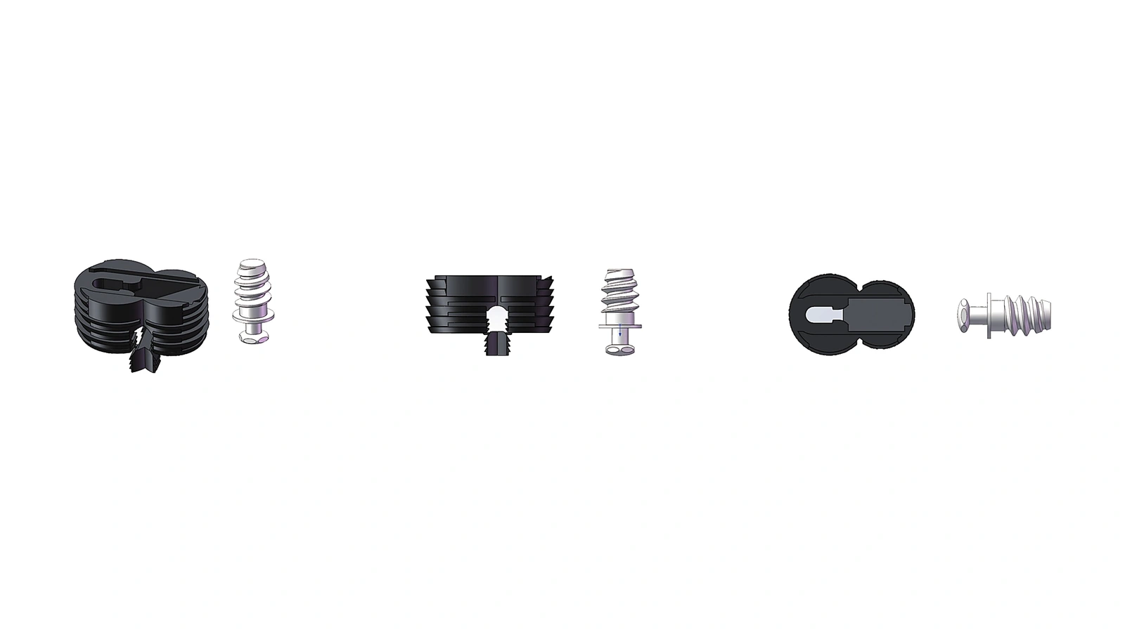
Tool-free final assembly does not mean machining-free production. D001 and D001-9 use a drilling path; S001 and S001-9 use a grooving path. The sample must be machined with the same method and setup intended for production, and the connector must be pre-installed before final assembly. If the machining coordinates or tooling details are not available in your documentation, mark them as items to verify with the connector supplier rather than estimating them.
Pre-installation is where many joint problems become visible. Check that the connector seats as intended in the prepared hole or groove, that the panel surfaces are not damaged, and that the pre-installed position matches the joint drawing. Record any deviation, because a sample that only works after rework does not represent a stable production process.
- 01Confirm the machining method: drilling for D001 and D001-9, grooving for S001 and S001-9.
- 02Machine the sample panels using the production setup and record the actual tool and parameters used.
- 03Pre-install the connector and check seating, panel condition, and position against the drawing.
- 04Document any rework or adjustment, since it affects whether the sample represents production.
Assemble the sample and record final engagement
During final assembly, observe how the joint closes, whether the connector engages without forcing, and whether the exterior surfaces meet as intended. These observations are qualitative but important: a joint that requires excess force or leaves a gap is a signal to review the machining and pre-installation steps before any load comparison.
If your evaluation includes load testing, record the conditions and results for the sample joint. Published tensile figures are 700 N for D001 and D001-9 and 900 N for S001 and S001-9; the listed anti-detachment figure is 200 N for these models. These figures do not replace testing in your board material and joint configuration.
- Joint closes without excessive force
- Connector engagement is consistent with the drawing
- Exterior surfaces meet as intended
- Any load observation is labeled as a sample result, not a guarantee
Review the record and decide the next action
Compare the sample record against the joint drawing and the intended production process. If the sample used a different board material, actual thickness, or machining setup, the result does not validate the production joint. In that case, the next action is to rebuild the sample to match production, not to adjust the catalog interpretation.
Before production approval, confirm the machining details and any application-specific panel-thickness requirements that remain open. Compare the sample against the drawing and repeat the test if the material, joint geometry or machining setup changes.
- 01Compare the sample record with the joint drawing and production process.
- 02Identify any mismatch in material, thickness, or machining setup.
- 03Record unresolved drawing and test-documentation requirements.
- 04Decide whether to rebuild the sample or proceed to production approval.
Connector comparison
Referenced models
Compare suitable connector models by application, panel thickness and machining method.
| Model | Process | Application and panel range |
|---|---|---|
| D001 | Drilling |
|
| D001-9 | Drilling |
|
| S001 | Slotting / grooving |
|
| S001-9 | Slotting / grooving |
|
Practical questions
Frequently asked questions
Does tool-free final assembly mean no machining is required?
No. Tool-free refers to final furniture assembly only. CNC drilling or grooving and connector pre-installation still occur before final assembly, and the sample must include those steps.
Can I use the catalog force figures as design limits?
Treat them as comparison inputs, not universal guarantees. Validate the joint in the intended board material and actual thickness, and confirm the test basis before using any value for engineering approval.
What information should I request before using load figures in a design?
Ask for the relevant test method and conditions, then validate the complete joint in the intended board material and application. Do not use an unclear catalog measurement as a design limit.
Which panel range applies to a 45° miter joint?
For D001-9, the 45° miter joint range is 18–25 mm; for S001-9, it is also 18–25 mm. Surface-to-surface ranges differ, so record the application on the drawing before machining.
Next steps